 |
|
|
 |
|
|
|
Build a Barn Door Tracker
Drive Mechanism
Ideas for many of the individual pieces were found at various web sites. Check the Helpful Links section.
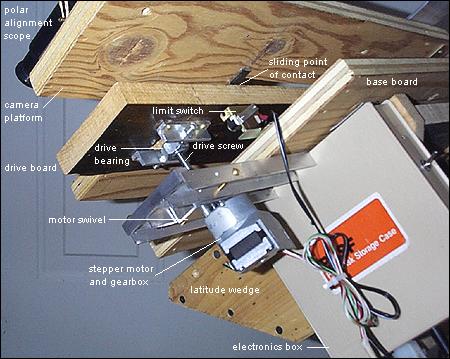
Base board. This 3/4" plywood base carries the drive assembly and the hinged ends of both the drive board and the camera platform. The base board is attached to the latitude wedge.
Drive board. This T-shaped component is made of pine. Its hinged end is attached to the base board, and the other end is supported by the drive screw.
Camera platform. Made of plywood, this U-shaped board carries the camera and the polar alignment scope. One end of the camera platform is attached to the base board with hinges. The other end rides along the drive board.
The shapes and relationships of the base board, drive board, and camera platform are best seen in this top view and this end view.
Sliding point of contact. Where the inner edge of the camera platform rests on the drive board is the "sliding point of contact." As the drive screw pushes the drive board upward, the surface of the drive board pushes against the the camera platform. These excellent diagrams illustrate the concept.
Many builders of barn door mounts apply a laminate (such as Formica) to the top of the drive board and attach a thin strip of Teflon to the edge of the camera platform. My design is less elaborate. The top of the drive board has a smooth, hard polyurethane finish. A piece of slippery Nylon cut from a large tie-wrap is glued to the edge of the camera platform. So far, this works fine, with no sticking.
Stepper motor and gearbox. I found this wonderful little 12-volt stepper motor for sale on AstroMart. It included a 30:1 planetary gearbox, making it ideal for this application. The motor operates at a 1.8° step angle, but with the 30:1 gearbox, the output shaft turns at a mere 0.06° per step. Unfortunately there are no more of these motor/gearbox combinations available from my source.
The output shaft of the gearbox is attached to the drive screw with a ¼" shaft coupler. The coupler needed to be threaded at one end to fit the drive screw but unthreaded at the opposite end to accept the output shaft of the gearbox. I purchased a threaded coupler, bored out one half of it, and drilled and tapped the bored end to accept a set screw to hold the coupler to the gearbox shaft.
My first attempt to motorize my barn door was not successful, because I used a stepper motor directly, with no gear reduction. I found that even a small amount of binding in the drive mechanism caused the motor to occasionally miss one or more steps, resulting in poor tracking. With its 30:1 gearbox, the current design has plenty of torque to overcome minor binding and small misalignments.
Drive screw. A 6" long ¼"-20 bolt is attached to the motor at one end and passes through the drive bearing at the other end. I cut off the head of the bolt with a hacksaw.
Motor swivel. To maintain alignment of the drive mechanism as the angle between the base board and drive board changes, the motor must pivot. To do this, I mounted the motor to a small piece of aluminum channel stock and suspended it between two support brackets, also made from aluminum channel. A pair of brass machine screws act as axles, and two brass washers placed between the motor mount and the brackets serve as bearings.
Drive bearing. Just as the motor must pivot to maintain alignment, so must the attachment point of the drive screw to the drive board. The drive bearing is made from a ¼"-20 nut which is press-fitted into a larger nut. The threaded opening of the larger nut must first be filed into a roughly hexagonal shape before the smaller nut can be pressed into it with a vise. Then, holes are drilled on opposing sides of the larger nut to accept supporting screws. The supporting screws are adjusted in their brackets so that the drive bearing assembly moves freely without binding.
Limit switch. During an exposure, the drive board is pushed away from the base board by the action of the drive screw. After a few exposures, the drive board must be "rewound." That is, the motor must be run in reverse to bring the drive board back to its "closed" position near the base board.
To prevent the two boards from coming into contact, which could damage the drive mechanism, a limit switch is used. This normally-closed microswitch opens when the drive board contacts it, removing power from the motor. This particular microswitch was salvaged from an old 5¼" floppy diskette drive, but similar switches are available from several component sources.
| ||||||||||||||||||||||||||||||||||||||||||||||||||||||||||||||||||||||||||||||||||||||||||||||||||||||||||||||||||||||||||||||||||||||||||||||||||||||||||||||||||||||||||||||||||||||||||||||||||||||||||||||||||||||||||||||||||