Further
Modifications of the CG-5 mount drive
By Paweł Łańcucki, Pawel.Lancucki@pl.ibm.com
Here I described
modifications of the original duaI-axis drive for use with the CG-5 mount from
Celestron.
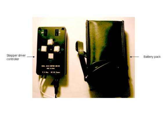
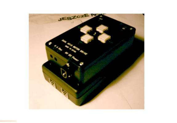
Electronic drive
Original dual axis drive
from Celestron consists of four main parts: two stepper motors with gear boxes;
hand controller, which includes all the electronics and connectors and power
supply in a form of a battery box accepting 4 R20 (D type) 1.5V cells.
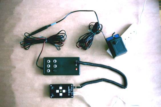
Components of the original
drive are shown below:
The drive is quartz
controlled and gives good accuracy for visual use. Main drawbacks of the drive
are:
- Backlash in gear trains;
- Lack of provision for use of external power
sources, like car battery or wall transformer;
- Hand controller usually cannot be conveniently
placed due to short leads to motors and to power supply.
Not a lot can be done with
the gears, so I decided to focus on rebuilding / rearranging the electronic
parts. I also decided not to play with the original printed circuit board
(PCB), but rather to connect external components to it. Also, I decided that
components build should be (as far as possible) compatible with a motorised /
computerised telescope drive as described by Mel Bertels.
The new electronic parts
consists of three main components (apart of the motors):
- Power supply
- Hand controller
- Stepper driving circuit
The
components were build exactly in the order described above to minimise any time
the drive is non operational – as described in the following text. The circuits
described below are very simple. The tools needed are those of a radio-amateur
and can be readily purchased in some stores (e.g. Radio Shack). I used a couple
of screwdrivers, small hand tools to cut or bond wires and component leads, 15W
soldering iron, small electric drill, fine files to make holes and universal
electronic multi-meter (I use mostly voltage, current and resistance settings
as well as a circuit continuity tester).
Just a word of warning – any
changes you do to any electronic components may and will violate the manufacturer
guarantee and therefore will be done at your own risk. If you are not confident
you can modify electronic components, ask a friend or limit yourself to the
power supply box only!
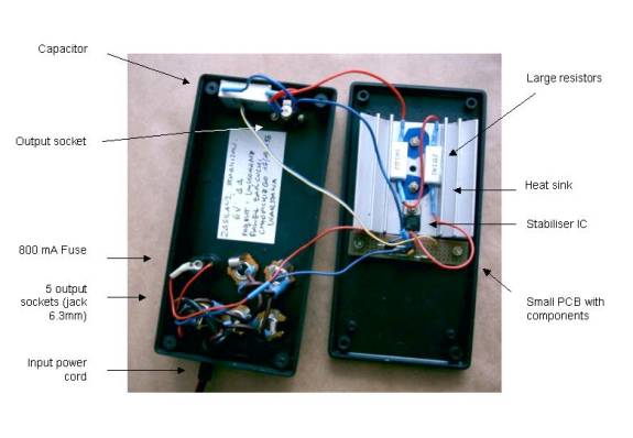
Power supply components are shown below:
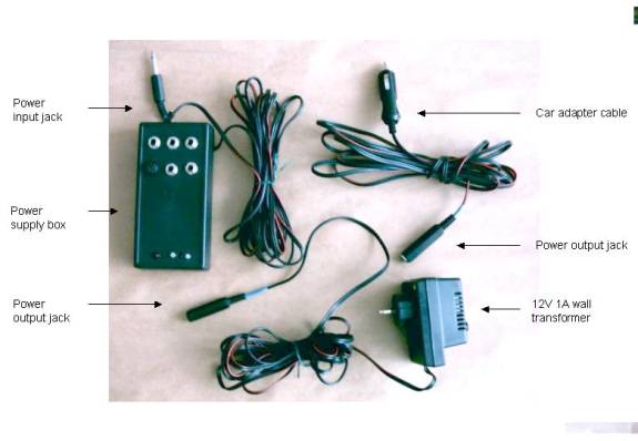
Power can be sourced from
220V mains (European standard), from 12V car battery or from any battery pack
capable of driving the scope through the night.
Celestron dual axis drive
requires 6V at approximately 500mA. However, a stabiliser IC cannot be
connected to it directly – the drive “hangs up” with higher power consumption,
ant this may cause stepper driving transistors to burn. Apparently the original
circuit uses internal resistance of the batteries to limit motor coil current,
so I taken a provision to include additional 2 Ohm resistance in the power
line.
At this time, I also decided
to use 6.3mm mono Jack plugs and sockets as a standard for all power supplies.
One 6.3mm mono Jack plug on a 3 m speaker cord (2 x 1.5mm2) provides
supply to the unit. Five 6.3mm mono Jack sockets are mounted on the front cover
and can be used to provide supply to other devices, like dew heaters, mirror
cooling fan, small CCTV camera etc. You may opt to increase the rating of the
power cord depending on your particular power needs, however, high power
consumption accessories or accessories generating electromagnetic noise should
use separate power supply. Front of the power supply box looks as follows:
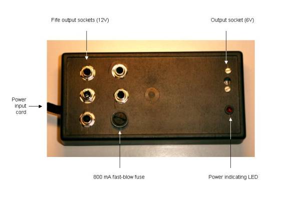
The entire power supply box
is housed in a small (ca 8 x 14 x 3 cm) plastic “project” box. Four mono “jack”
sockets are not fuse protected and can be used to supply power to auxiliary
devices.
The power supply box circuit
diagram is shown below:
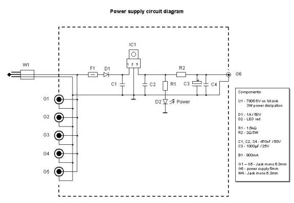
Power supplied to the drive
electronics is protected by 800 mA fuse F1. Diode D1 - 1A/50V - protects the
circuit from reverse polarity in input lines. Power is the conditioned by an IC
stabiliser IC1 - LM7806 - down to 6V. It should be mounted on a heat sink to
dissipate 3 – 5W of power. In my case, I have used ca 100 cm2 heat
sink with tree-like fins, which heats warm in use but actually never overheats
even after many hours of use. Two small capacitors C1 and C2 – 470nF/50V are
necessary to prevent unwanted oscillations of the IC. Small red LED diode D2
fed by resistor R1 - 1.5kW
1/4W - is mounted on the front cover and confirms that the power is on. Two 1W resistors rated 1W each (shown as R2) simulate the
internal resistance of the battery pack, and output capacitors C3 – 1000mF/25V and C4 – 470nF/50V are necessary to moderate
any current spikes caused by stepper switching circuit. Internal electronics is
shown here:
Finally, power is fed to the
stepper driving circuit by 1.5m of 0.5mm2 wire with standard “power
supply” plugs on both ends. In my case, I used a spiral wire form an old headphone
set. However, I may opt in future to exchange these plugs because the standard
plug tends to slip out of the socket in the stepper controller!
Any voltage between 9 and
15V can be applied to this unit, however it should be compatible with power
requirements of any auxiliary devices connected to jack sockets. Direct
connection to car battery (12V) or 12V wall transformer (unregulated) is
usually adequate. To complement the power supply box I have made a car lighter
to jack socket adapter cable and one 10 m (30 ft) extension cable, which
extends the use both in my yard and in field. Also, a jack socket was mounted
on the end of cable from a commercial 12V wall transformer to provide supply
while using the scope in my backyard. Warning – I always place the wall
transformer in house and use 10 m extension cord. Bringing a wall transformer
outside may create a risk of electric shock!
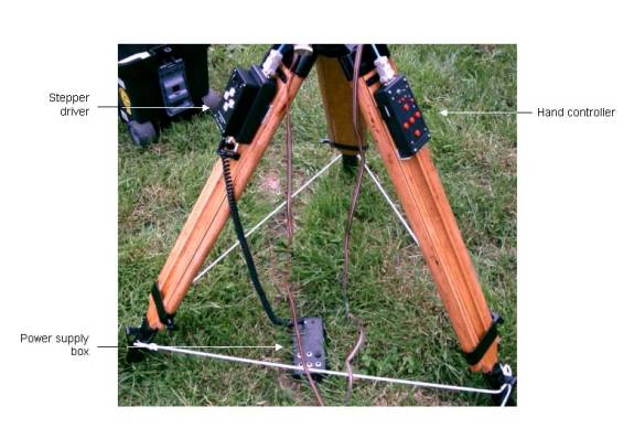
You can prepare the power
supply box without any changes to other components, while you continue to use
the battery pack. Once the power supply box is complete, you can start to use
it immediately even if you do not plan to make any other modifications. Here,
the power is supplied from a wall transformer through the power supply box to
the original hand controller:
Hand controller is slightly more complex. The front panel is shown
below:
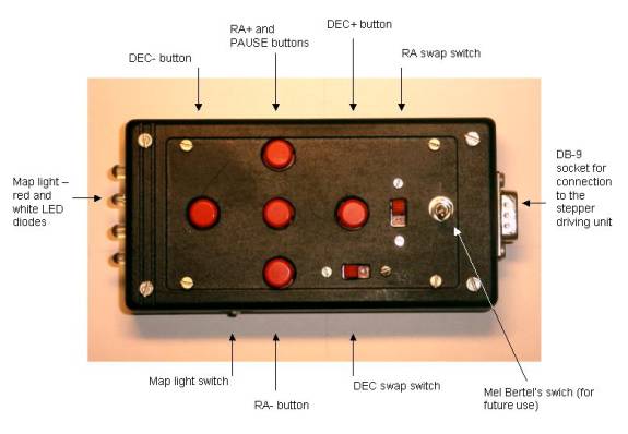
The main features are:
- Four direction buttons (N, S, W, E or RA+, RA-,
DEC+ and DEC-), which actually duplicate the direction buttons on the
original controller box. These buttons operate at the speed set by the
switch at the original controller box – 2x, 4x or 8x.
- Pause button. I decided to include it for
astrophotography use because the original 2x speed switches the RA stepper
motor into opposite direction and all backlash in the gear train prevents
the mount from reacting quickly. It will also operate as an “enter” button
while connected to the Mel Bertel’s computer controlled drive.
- Two direction control switches. The simply
reverse operation of pairs of direction buttons to make the unit more
intuitive to use.
- One three position switch which does not have a
function allocated at the moment and is build in for future use with Mel
Bertel’s computer controlled drive.
- One three position switch which activates map
lights. I have used two bright red LED diodes to get “night vision” red
light preserving eye accommodation, and two bright white LED diodes to
read colour coded maps. Order of switching is OFF à RED à White.
The hand controller circuit
diagram is shown here:
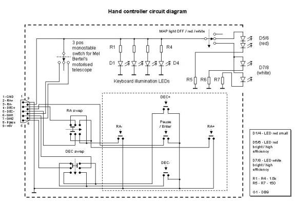
All buttons operate by connecting appropriate output line to
ground, while in a “non-active” state, output lines are “floating”.
Fife small mono-stable press
switches are used for direction and pause buttons. Pause button is connected
directly to the output socket. Direction buttons are grouped in pairs (N+S and
W+E) and connected to two switches, which reverse operation within each pair.
Output lines of the switches are connected directly to the output socket.
The three-position switch
output lines are connected directly to the output socket.
Another three-position
switch is used to activate LED map lights. Two diodes are used for both red D5
/ D6 and white light D7 / D8. Configurations of diode pairs and current
limiting resistors depend on required diode voltage and were adjusted to get
20mA current through each diode – this gives a decent brightness without
possibility to burn the diode. In my case, red LED diodes are connected in
series, while white LEDs are connected in parallel, with separate current
limiting resistors. In my case, all resistors turned to be 150W. Power supplied to diodes by one of the connecting
lines is connected to the stepper driving circuit. The voltage may vary when
steppers are in the sleeving mode, but the changes in LED brightness are negligible.
Finally, four small LED
diodes D1 to D4 with current limiting resistors R1 to R4 (all 1.5kW) are connected directly between power supply and
ground. They glow dimly in the night and provide very dim backlight to the
controller buttons. Actually, you may opt to use resistors of even higher
value, depending on the required level of button backlight. Values shown here
were tested in a decent dark, but not ink-black environment.
All resistors are rated
1/4W.
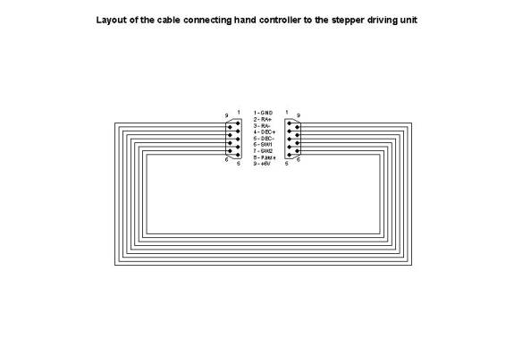
A DB-9 “computer type” male
socket is used to output the controller lines. The individual pins’ functions
are as follows: 1 – ground, 2 – RA +, 3 – RA-, 4 – DEC+, 5 – DEC-, 6 – three
position switch pos1, 7 – three position switch pos2, 8 – pause, 9 – power
supply 6V.
A custom made cable with 9
lines and male / female plugs on both ends connects the controller to the
stepper drive. I used soldered joints, which are very reliable. I decided to
make the cable in a way which enables easy replacement or extension – see
below:
Most of components were
mounted directly on a universal printed circuit board 100 x 60 mm, which is
held inside a black plastic project box 120 x 65 x 20 mm. This size is a good
compromise between ease of assembly and convenience of use.
Two direction reverse
switches and extra switch for computerised drive were mounted on the cover of
the box.
The order of operations was
as follows:
1
Select a plastic
project box which fits your hand and which will accommodate all components.
2
Select a universal
printed circuit board and cut it to fit inside the project box. Prepare
mounting holes / spacers to secure the board inside the box.
3
Select positions for
direction / pause buttons and mark PCB holes which coincide with centres of the
switches. Next, drive a thin (1.5mm) drill through the board while mounted to
the box – this will ensure that buttons will mat the holes after they are
soldered. Make button holes slightly oversized – for my 9.5mm buttons I made
10mm holes.
4
Cut or drill remaining
openings in the box – for direction reverse switches, MEL Bertel’s switch, DB-9
socket, 4 LED diodes and light switch.
5
In my case, I had to
cut or drill holes in the printed board to provide clearance for switches which
are attached directly to the box cover.
6
All drilling / cutting
should be completed before you start to assembly the electronics. While
assembling the electronic components, always check for fit to the prepared
holes / openings.
7
Carefully solder all
components – one at a time. I started with LED diodes as they must match the
holes in the box. Next – direction buttons, diode driving transistors /
resistors and small LEDs and their resistors. Finally, connect the components
which are mounted outside the printed board (direction reverse switches, MEL
Bertel’s switch and DB-9 socket) with short lengths of thin stranded wire – I
used small pieces cut off a 10 strand tape.
8
Check proper resistance
for the current limiting diodes before soldering the components – I did it by
just connecting diode and resistor to 6V power supply and ground leads carrying
these components in hands, while watching the readout of my mili ampero-meter.
Also, check all buttons / switches before assembly – they are quite difficult
to take apart from the PCB once they are mounted.
9
As I used an universal
PCB, there was a need to connect individual printed paths of the board. I made
these connections from cut-over resistor / diode pins (short ones) or from very
thin stranded and insulated wire (longer ones).
10
After soldering each
component, check for possible bridges between adjacent printed paths. In case
of doubt, check with resistance meter. All eventual bridges must be cleared
right on spot, as they will be even more difficult to remove after more
components are attached.
11
I always solder one
component or one group of components at a time and take few moments to test the
circuit. In case of any problem, it can be contributed to the most recent
mounted components. This is a very practical advice – I did quite a bit of
custom electronics development and it always pays to do as much testing as
possible at various assembly stages.
The entire controller can be
mounted in three – four evenings – one to do the machining and the rest to
solder and test the circuit. You can continue to use the original drive while
you build the hand controller, so there is no rush – just do it well.
Those who already know the
design of the Mel Bertel’s computer controlled drive have already noticed that
the hand controller is not entirely compatible with the drive – in particular
the buttons and switches do not operate in required way. I decided to make the
hand controller more suitable for the current use, while compatibility with Mel
Bertel’s computer controlled drive will be achieved by adding some ICs to
properly decode buttons and switches at a later stage.
Stepper driving circuit is the most tricky part, because you actually need
to play with the factory made PCB .
Also, you cannot use the drive while the original stepper driving circuit is
disassembled.
I decided to retain both the
original stepper driving circuit as well as its plastic housing. The add-on
components are mounted on a separate universal PCB, which is housed in another
plastic project box – a twin to the hand controller. The original driver box is
“piggy-backed” on the add-on components box (glued with double sided tape and
fixed by four M3 screws), both circuits are connected by a number of wire
strands which pass through a couple of holes between both boxes.
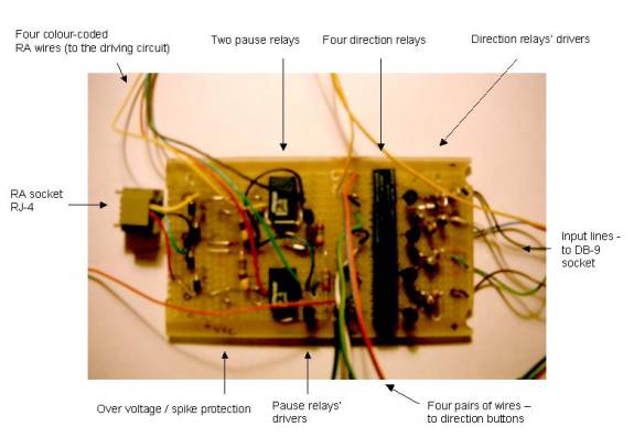
The stepper driving circuit
diagram is shown below:
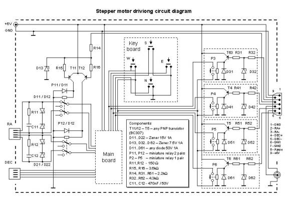
Direction buttons (N, S, E,
W) of the hand controller drive four identical amplification circuit. I used
these amplifiers to make my circuit compatible with auto guiding units. In a
low input state, the driving unit must be able to sink less than 0.5mA –
typical MOS ICs can sink up to 2.5mA, while TTLs can sink up to 10mA.
Therefore, this unit is quite safe to use with commercial auto guiders.
I will describe operation of
the amplification circuit based on the RA+ line. Input line is connected to a
base of a low-power PNP transistor T3 through a network of two resistors R31 –
2.2kW and R32 – 4.3kW and a protective Zenner diode D32 – 7.5V 1A. This
circuit will ensure that the transistor is saturated (open) while the input
voltage is close to ground, but it will also protect transistor from damage in
case a high or low voltage is accidentally connected to the input line.
Transistor T3 operates miniature relay P3, which in turn duplicate the function
of the existing direction buttons. Therefore, the internal circuit of the stepper
driving circuit is separated from any voltages that may appear on the input
lines. Transistor is protected from any voltage spikes which can be caused by
turning on and off inductive load of the relay coil by a reverse polarised
diode D31. Normally open pairs of relays’ contacts are connected by pairs of
thin wire (cut from 10 wire colour tape) to the back of the button PCB from the
original controller. Make sure that RA and DEC buttons are not mixed. Actually,
it does not matter if you connect RA+ relay to the West or East button of the
stepper circuit – if the operation of the buttons is opposite to what you
desire, simply put the swapping switch on the hand controller in a second
position!
The pause button operation
is slightly more complex. Ideally, I should rather disconnect coil driving unit
from the micro-controller on the original PCB. However, I did not want to play
with the original PCB, so I used two small relays P11 and P12, which disconnect
two RA motor coils from the driving circuit. Suddenly switching the coil
inductance from the current supply generates voltage spikes that could over
time destroy small contacts of the relays. Therefore, on both coils I used a
spike protection circuit consisting of 150W 1/4W resistor R11(R12) and 470nF capacitor C11
(C12), connected in series. Furthermore, two 15V 1A Zenner D11/D12 (D21/D22)
diodes cut-off any over-voltage spikes.
Instead of simply
re-connecting the motor wires to the relays, I used two RJ-4 sockets – this
enables me to use any standard telephone cable as connection between the
driving box and stepper motors. Coiled telephone cables are by far more
convenient in use and also can be easily replaced in case of any damage!
The whole stepper driving
circuit consists of two main components:
- original stepper driver (hand controller)
- relay board which houses all additional
components.
Close-up of the original
drive controller unit interior is shown here:
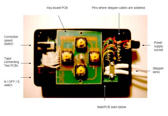
Here you can see it after
the key-board was removed:
And here there is a close-up
of the relay board:
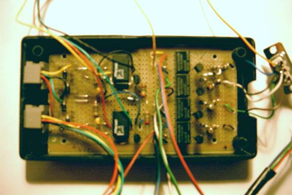
Here is shown how it looks
inside the plastic box:
The order of operations was
as follows:
1
You do not need to play
with the original drive before the relay board is completed and tested – start
with it!
2
Select a plastic
project box which will accommodate all components. In my case, it was identical
to the hand controller box.
3
Select a universal
printed circuit board and cut it to fit inside the project box. Prepare
mounting holes / spacers to secure the board inside the box.
4
Cut and drill openings
for RJ-4 sockets (to motors) and for DB-9 socket (connection to hand
controller).
5
Lay the largest
components on the PCB. I opted to put relays in two groups – four relays which
operate direction buttons are mounted closer to the hand controller socket,
while two remaining relays which operate the pause function are mounted closer
to the RJ-4 connectors to motors. I left a lot of space around the relays to
mount other components (drivers / amplifiers, relay protection etc.).
6
Before soldering relays
check them for polarity - my pause
relays did not work until the driving voltage was applied to the coil in a
specific. Also, check which pins correspond to the relay contacts, which will
be opened and which closed before and after applying power supply. I used 6V
relays, which still operate safely while powered by a lower voltage (the supply
may drop by 0.5 to 1 volt due to the current consumption by stepper motors and
additional 0.4 volt for driving transistors).
7
If you have an
opportunity, check the transistors for their current amplification coefficient.
It should be at least 100 - 120, and preferably around 200 to ensure proper
operation of relays.
8
Connect two power
supply lines – red for positive and white or black (or any other, just remember
the colour) as negative.
9
Lay and solder all
other components. I started with direction relays. Again, I opted to assembly
one relay circuit at a time. After each section is completed, solder a short
coloured wire as an input line and test this section by connecting the input
line to the ground – you should hear the relay to click while switching. If you
don’t, check that particular section.
10
Attach pairs of thin
wires to the connecting contacts of the direction relays. It helps to use
colour-coded pairs from a 8 or 10 wire tape. Please note which colour
corresponds each relay and save this information until you connect this pairs
to the button board.
11
Solder all input lines
to the appropriate pins of the DB-9 socket. Also, remember to connect power
supply and ground lines to DB-9 socket – otherwise the hand controller would
not work!
12
Connect the RA RJ-4
socket to the pause relays. Please note the colour coding of the RJ wires. Red
and green wires should be connected to one relay while black and yellow to the second
– this pairs drive two stepper coils and need to be connected to the
over-voltage / spike protection circuit.
13
Connect a 4 wire tape
to the pause relays – each of 4 wires between the original controller and the
RA motor will be disconnected. Please use the same wire colours as the ones
which were just soldered from the RJ socket – this colours will be important
while you will connect these wires to the stepper driving board - this tape
will be later soldered to the output pins of the RA line. All these tapes and
wires should be quite flexible!
14
There are two pins (6
and 7) left on DB-9 socket – they correspond to the three position mono-stable
switch. You may leave them not connected – I opted to connect them (and power
supply and ground) to a small auxiliary socket, they can be used to control
motorised focuser in the future.
15
Apply 6V power to the
proper power lines (warning – this circuit has no protection from reverse
polarity of power voltage!) and perform a final check of the relay board – all
components should operate properly, hand controller buttons should cause relays
to switch. Check if the two wires in each pair get closed as you push hand
controller button, check if the RA lines get opened as you push pause button.
Also, LED diodes on the hand controller (keyboard back-light and map light)
should get lit.
16
Until at this moment,
you did not need to play with the original controller. But now it is the time!
17
Place the original hand
controller on a clean surface. Prepare plastic bag or box where you will put
various components and screws – you ill need them back to complete the
assembly! Also, prepare an anti-static bag or box to safely store the driver
circuit.
18
Please obey the
anti-static precautions while handling the drive components – any electrical
components can be easily destroyed by static which builds up on our body and
clothing. The best option is to use an anti-static wrist band connected to
ground by 1M resistor – I have purchased one some time ago in Radio Shack. Get
your soldering iron grounded and avoid touching electrical components on PCBs.
19
Carefully remove four
direction buttons’ caps, remove two screws mounting the power supply socket and
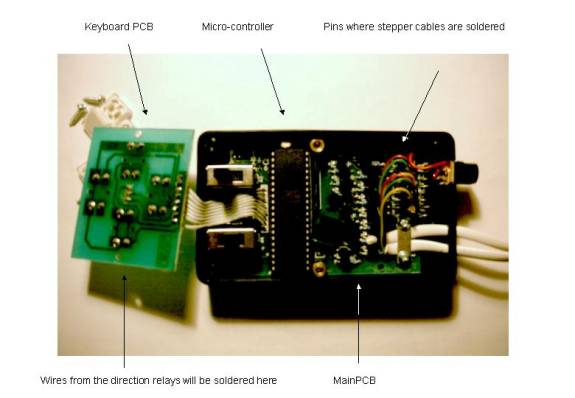
four screws holding the cover. Carefully remove the cover. You will see two
PCBs – four buttons and one two-coloured LED are mounted on the top board,
while the micro-controller and driving units are mounted on the “main” board on
the bottom. Both boards are connected by a multi-wire tape.
20
Remove two machine
screws holding the keyboard PCB. Locate and remove three remaining screws
holding the main board.
21
Locate ten pins where
all external cables are soldered. There are two stepper motor cables four wires
each and a pair of power supply wires. Consecutive pins are isolated. If you
look at the board while these pins are closest to you (natural position
according to the printed labels on the cover), RA cable will occupy four
leftmost pins, DEC cable four central pins and power supply two rightmost pins.
Please note on paper colours of wires which are connected to all pins – this
will be crucial later.
22
At this moment you will
have to disconnect both RA and DEC cables. Do it carefully and remove cables
from the controller box.
23
Carefully remove both
boards from the housing – pay attention not to destroy the tape connecting both
PCBs. Place the PCBs in an anti-static bag and put aside for a while.
24
Attach the bottom part
of the original controller box to the cover of the relay board housing. Pay
attention to ensure that you can attach the cover to the relay box – places for
screws must be left clear! Also, the RJ-4 sockets should be located close to
the output pins of the controller, while the DB-9 socket for hand controller
should be located closer to the keyboard side. I used some pieces of a double
sided tape to hold the together. Next, I drilled four 3mm holes through both
boxes. Four M3 machine screws and nuts are used to keep both boxes together – I
secured the nuts from turning out with small drops of paint.
25
Finally, drill two
large 10 – 12 mm holes between the boxes – all interconnecting cables will pass
through the holes. Clean the boxes (and your workshop) from any pieces of
plastic or dust left after drilling.
26
All drilling / cutting
should be completed before you continue to assembly the electronics.
27
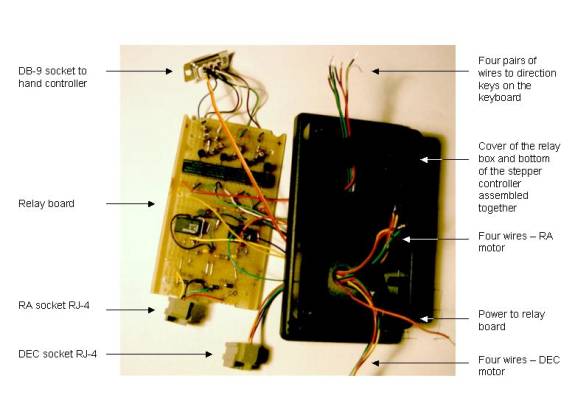
Pass the wires and
cables from the relay box through the two holes up to the driver box. Do not
forget to pass the wires from the DEC RJ-4 socket as well!
Here you can see this stage
of the project:
28
Take the driver PCBs
out of the plastic bag and put them back in the box.
29
Carefully solder RA and
DE socket wires to the appropriate pins on the driver PCB. Pay attention not to
mix RA and DEC wires and to solder colour coded wires to exactly the same pins
as before!
30
Solder the relays box
power supply directly to the power socket.
31
Solder pairs of wires
to the keyboard PCB. At there is no place to attach these wires on the
components side, solder them directly to printed paths below the direction
buttons. Ensure that RA and DEC pairs are not mixed (RA + or – can be connected
to any of the W or E buttons – you may only need to swap the button reverse
switch on the hand controller).
32
Now it is a time to
check the entire system. First, double and triple check visually that all wires
are connected properly. Check for any short-circuits between the power lines
and between the output lines of RA and DEC motors.
33
Connect the hand
controller to the DB-9 socket and connect RA and DEC motors to appropriate RJ-4
sockets. In my case, location of sockets correspond to the labels on the
controller cover.
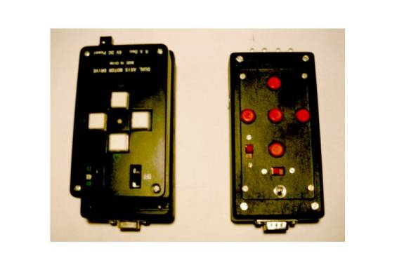
Here you can see the stepper
driver side by side with the new hand controller:
34
Put the power switch in
central (OFF) position and apply power supply. Keyboard illumination LEDs
should get dimly lit. Hand controller buttons should operate appropriate
relays.
35
Switch the power switch
to N. RA motor should start (you can hear it). Check if the original buttons
still operate the RA and DEC motors. Next, check if the hand controller buttons
operate the motors as well.
36
Check if the pause
button stops the RA motor.
37
If everything went
well, you are ready to finally assembly the drive electronics. Otherwise,
switch the drive OFF and continue testing to isolate failed component or
connection.
38
Press the stepper
driving PCB back into it’s place. You may slightly pull the wires from the
relay board side – there will be lot of place left for wires in the relay board
box.
39
Attach three small
screws securing the main PCB. Attach the keyboard PCB using two machine screws
– be careful, you may need to press cables that are soldered on the soldering
side flat before you can tighten these screws.
40
Put the cover in place
and attach it using four screws. Attach power supply socket. Put button caps in
place.
41
Attach the relay board
inside the box. Make sure that all cables fit inside the relay box and attach
the cover with four screws.
42
Perform a final check –
just in case any wire or joint got broken during this final assembly stage.
The stepper driver
piggy-backed on the relay box:
Congratulations – you have
completed an important step – your modified dual axis drive was modified and is
ready to use! You may need to find a place to attach the drive to the tripod of
your mount. I opted to attach the drive electronics with a self-adhesive Velcro
tape, while the hand controller is held in a bracket made form 25mm x 1mm
aluminium tape – it allows the controller to be easily taken in hand without
pushing the telescope mount.
Field tests
My drive was tested after
the modification during several nights of observing. The modification proves to
be very helpful – with my 3.5m cord I can easily take hand controller to the
eyepiece and use it to center a planetary nebula in a field of a
high-magnification eyepiece, while moments later I use the map lamp to look in
my Star Atlas 2000 for next object to observe.
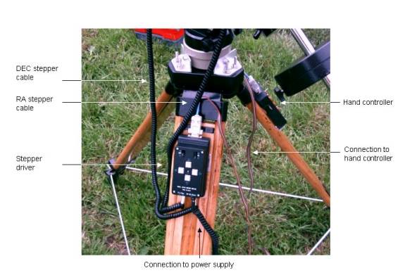
And the close up of the
connections to the stepper driver:
I didn’t try auto-guiding
yet, but I think it will be possible with this modified drive, as I have
already checked the drive reaction. First, I put the mount slightly out
of balance in RA to make the motor work “upwards” – this eats any gearbox play.
Then, I simply use the RA+ button at 2x speed to sleeve the scope westwards,
and use pause button (and the diurnal motion of the sky) to sleeve the scope
eastwards to correct the periodic error. From my eyepiece impression at over
200x, the mount reacts almost immediately, definitely a couple of times faster
than if you reverse the direction of the RA drive! I think a similar trick with
slight imbalance can also work for DEC axis. Also, it may be easier to track in
declination if you correct only in one direction – very slight offset of the
polar axis off the true celestial pole can do this, but will also limit useful
exposure times due to the field rotation.
Final notes
Just a few final notes on
building electronic devices:
- It always pays to buy 1 – 2 more components – if
one get damaged during assembly, you will save a trip to the shop.
- Use only new components. If a component has any
of physical damage, discard it. Even if it works initially, the
probability of failure is greater.
- In case of any doubt, always check components.
Even simple multi meter will help. Resistors can be easily checked for
their values. Discard any resistor if the value is outside +/-20% of the
nominal value. Diodes can be checked using diode checking setting on the
multi meter. If you do not have one, you can use 9V battery, LED and
1.5kOhm resistor in series. For transistors the best way is to check their
current amplification coefficient. Switches and relays can be checked
using circuit continuity checker.
- While working with the main board of the stepper
controller circuit, I recommend to use an ant-static device to prevent
damage to the micro-controller.
- Use small soldering iron. Precision 15 W model
is the best choice.
- Plan assembly in advance. Some components may be
easier to mount on the PCB if they are soldered first.
- Always perform lots of tests after new component
or few components are added. Any failure can be contributed to the
components most recently added, so check them first. Isolating a problem
in a complex circuit may be quite difficult.
- Faults may be contributed to failed components,
bridges shorting traces on the PCB, small hair-like wires shortening soldering
points, broken wires inside the insulation (rare), broken joints of wires.
- Mechanical components (plugs, sockets, switches,
buttons, relays) tend to fail first.
- If the soldered components are dirty, if you
solder to shortly or if the temperature of the iron is to low, you can get
a “cold joint”. Cold joint may look as a proper one, but will contribute
noise and eventually will break. For good joints, the soldering time
should be approx. 2 – 3 seconds.
- Do not overheat components – the soldering time
should not be longer than few seconds.
- Large components (e.g. capacitors) tend to tear
joints away from the PCB if exposed to shock - due to their large mass. To
relive some stress from joints, you can secure these components by
alternative means – e.g. using silicone adhesive. If a component has
mounting holes – simply use small machine screws and nuts to secure it in
place.